Exploring the Working Principle of Micro-ohm Meters & Their Different Types
Contents
When troubleshooting, repairing or just testing electronic equipment, you need to use different types of test equipment in order to test the proper circuit currents, voltages, and resistances to decide whether the wiring is faulty. Ohmmeters are one of the most common pieces of equipment used for this purpose and without understanding them you can not connect the instrument to a circuit to test the component. Ohmmeters are designed with different levels of sensitivity. Some of them measure low-resistance, while others are designed to measure high-resistance materials.

What is an ohmmeter and what are the different types?
Ohmmeters are electronic instruments which are widely used for measuring the resistance of a circuit element or checking a complete circuit. Different types of ohmmeters are used to measure resistance in different applications of electrical testing.
- Micro ohm meter – This instrument is generally used for bonding contact applications and for measuring extremely low resistance with high accuracy at particular test currents. It is a small portable device that measures voltage, current and test diodes. It comes with more selectors so that you can choose the needed function. When it comes to buying a micro ohm meter, there are two types: 10A micro 100+A micro ohmmeters. The first model is a go-to choice for most operators as it’s designed to cover most field applications. It is lightweight and features improved battery operation. There are 10A micro ohmmeters that have different measurement modes addressing different types of testing conditions. On the other hand, 100+A ohm meters are designed for testing contact resistance of high-voltage. Cable joints, cables, welds and bus bars are all tested with the help of this electrical instrument.
- Milli ohmmeter – This type of instrument is generally used for general circuit and component verification. It is more affordable and less sensitive than the digital micro ohm meter which makes it a great choice if sensitivity and measurement resolution are not important.
Transformer ohmmeter – This ohmmeter is designed specifically for measuring transformer windings and tap changers. Some models are equipped with dual meters which means they can measure low and high resistance windings at the same time. They are multi-current devices that can be used for factory tests, field operating verification, for locating defects in transformers as well as for performing heat runs for determinating internal temperature changes. - Applications for the milliohm and micro ohmmeter
If you were wondering how does a micro ohmmeter work, it’s worth mentioning that micro and milli ohmmeters are used for a number of different applications due to the high accuracy readings of these instruments. Some of the applications include switch and contact breaker resistance, static control circuit and aircraft frame bonds, cable joints and bus bar, integrity of welded joints, quality control of resistive components, inter-cell connection on battery systems, motor and transformer winding resistance, pipe and rail bonds, cable and wire resistance, lighting conductor bonding and transmitter aerial, etc.
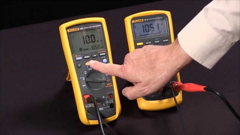
The next thing you might be wondering about is probably how to read an ohm meter. You should set your multimeter to the highest resistance range there is. The resistance function is typically denoted by the unit symbol for resistance: the Greek letter omega (Ω), or sometimes by the word “ohms.” Join the two test probes of your meter together. Once you do, the meter should register 0 ohms of resistance. If you are doing this with an analogue meter, you will notice the needle deflect full-scale once the probes are put together and it will return to its initial position when the probes are pulled apart.

Electrical resistance
Both of these instruments measure electrical resistance. The resistance is a measure of the difficulty to pass an electric current through a conductor. Electrical resistance is determined by the material and the shape of a conductor. What this means is that it is harder to push charged electrons through a thick and long wire made of a poor conductor than to push them through a thick and short wire made of a good conductor.

Technology
Things have changed a lot when it comes to measuring electrical resistance. The first models of ohmmeters were based on a type of meter known as a ‘ratiometer’, while today’s instruments have an electronic circuit that measures the voltage across the resistance and one that passes a constant current through the resistance. Standard ohmmeters use a two-terminal, simple measurement technique while milliohm and micro ohmmeters use a four-thermal measurement technique known as ‘Kelvin sensing‘. The two terminals are used for current sensing while the other two are used for voltage measurement.
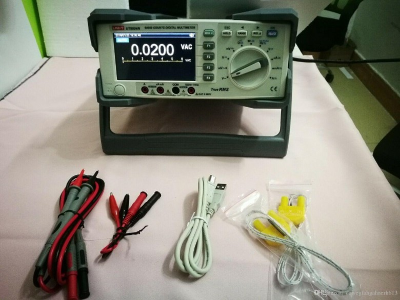
Both of these types of instruments are available in either handheld or benchtop models. Each of them has its own specifications for accuracy, test ranges, resolution and sampling rate. Some models may also include an adjustable sampling rate, data logging capabilities, auto-ranging, selectable ranges, advanced software, multiple channels, advanced communications for transferring measurements to printers and computers, scaling functions, temperature compensation and comparator functions.
Buying tips
Do you prefer a handheld or a benchtop model? What test range do you need? What is the suitable accuracy? Do you need any additional accessories? What functions do you need? Do you need data logging? Answering these simple questions will help you narrow down the options and choose the most suitable ohmmeter for the application.


